Home About Products RF Antenna Tracker GNSS Anti-Jamming Modules MIMO Mesh Data Links IRIG-106 Telemetry Receiver IRIG-106 Telemetry Transmitters Video Encoders News Careers Contact
Bridge · MIMO Mesh Datalink

Jam this.

Starting from $3,499 USD

ITAR-free·Ships in 8–12 weeks

A 100 W jammer already tried. We flew straight over it in DSSS mode and the link never dropped. Bridge spreads below the noise floor where a narrowband jammer has nothing to lock onto — and when hopping is the better answer, it hops the full 400 MHz to 6 GHz in a millisecond. Every node relays for every other node, so there is no single radio to kill. Go ahead. Jam it.

400 MHz – 6 GHz MIMO Mesh Jammer-Proven
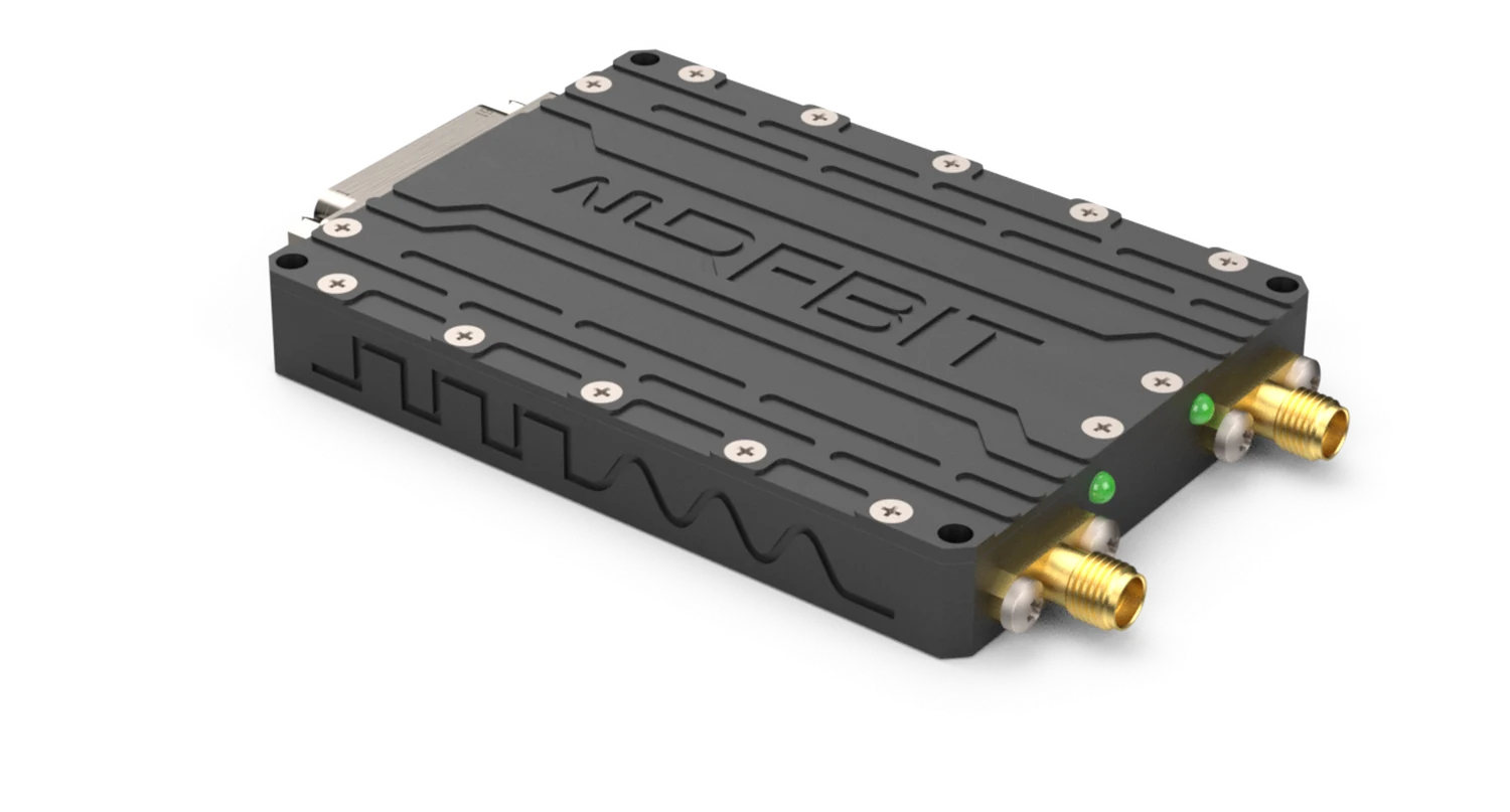
Bridge MIMO mesh datalink module
100 W Jammer Overflown
0.4 – 6 GHz Hopping Range
1 ms Hop Time
200 g 130 × 90 mm
Explore
The Problem

A link that needs clean spectrum
is a peacetime link.

The band is crowded before anyone starts jamming it. Add a deliberate emitter and a conventional narrowband link has nowhere to go — it sits at one frequency and waits to be found. Point-to-point makes it worse: one radio fails and the mission ends with it, because there was never a second path to the aircraft.

Bridge was built around both problems at once. Spread the signal so it cannot be picked out. Spread the network so no single node carries it.

Spectrum analyser, 2.4 GHz centre, 250 MHz span. The link carrier stands 40 dB above the noise floor, until a wideband jammer comes up underneath it and lifts the floor over the carrier. Thirteen seconds from clean link to nothing.

Live Test

We flew over a 100 W jammer.
It couldn't stop us.

Live Test Jammer active. Link up. Real-time footage

In live testing a Bridge-equipped aircraft overflew an active 100 W jammer in DSSS mode. The link held — no dropout, no reacquisition, no operator intervention.

100 WJammer Overflown
ZeroLink Dropouts
DSSSMode Under Test

Anti-Jam

Three ways to stay up
when the band is contested.

Anti-jam is not one feature. Bridge attacks the problem on three separate axes — hide the signal, move the signal, and push the signal only as hard as the mission needs.

01 — Spread it: DSSS and FHSS

In DSSS mode Bridge spreads its signal across a wide bandwidth and transmits below the noise floor. There is no carrier standing above the noise for a narrowband jammer to attack. On the receive side, processing gain despreads the wanted signal and pulls it back out of the noise while the interference stays spread and weak.

400 MHz 6 GHz Noise floor

DSSS — the signal is spread flat beneath the noise floor. The jammer has no carrier to find.

02 — Move it: 400 MHz to 6 GHz in a millisecond

When hopping is the better answer, Bridge hops faster than a jammer can follow. Automatic frequency hopping across the full 400 MHz to 6 GHz range with a 1 ms hop time and no limit on hop count. A continuous interference-avoidance algorithm steers the pattern away from channels it sees as occupied instead of hopping blindly into them, and ahead of the demodulator a receive-side filter bank suppresses interference before it ever reaches detection.

Full-span sweep, 400 MHz to 6 GHz. The carrier is never in the same place twice.

03 — Push it: adaptive output power

Output power is software-adjustable on every model, from 2 W to 20 W per TX channel depending on variant. Raise it when the link needs margin; drop it when it does not. Transmitting only as loud as the mission requires means a lower probability of detection — the quietest link is the one an emitter locator never finds in the first place.

DSSSBelow the Noise Floor
1 msHop Time, 400 MHz – 6 GHz
UnlimitedHop Count
AdaptiveOutput Power

The Mesh

No node
is the network.

Bridge is not a point-to-point radio with mesh bolted on. It is a distributed, centerless network: point-to-point, point-to-multipoint and multipoint-to-multipoint, in star, line, network or hybrid mesh topologies, with Layer 2/3 dynamic routing and multi-hop relay.

There is no master node. Kill any node — the network heals around it.

All nodes up — traffic takes the shortest path.

CenterlessNo Master Node
Layer 2/3Dynamic Routing
Multi-HopRelay

One waveform, one ecosystem: every Bridge model — from the 2 W airborne unit to the 20 W ground node — speaks on the same mesh.

Modulations

One radio.
Every waveform you need.

The waveform is not fixed in hardware. Bridge runs the whole ladder, from the most robust binary schemes through to dense high-order QAM and multicarrier TD-COFDM, and moves along it as conditions change.

Low on the ladder you buy range and resilience at the cost of rate. High on the ladder you buy rate at the cost of margin. TD-COFDM sits apart: spreading the payload across many subcarriers makes it the tool for heavy multipath, where a single-carrier waveform of the same rate would fall over.

Robust

BPSK · QPSK

Longest reach, lowest rate. The fallback that keeps a link alive.

Constant Envelope

FSK · CPFSK · SOQPSK

Kind to the power amplifier, spectrally contained, resistant to non-linearity.

High Order

16 / 64 / 256 / 1024 QAM

Maximum bits per symbol when the link budget allows it.

Multicarrier

TD-COFDM

Payload spread across subcarriers — the answer to severe multipath.

Video Pipeline

Plug the camera in.
That's it.

FLIR raw-output cameras connect directly over GigE Vision or USB. Bridge ingests 500 Mbit–1 Gbit of raw video, compresses it onboard with H.265 and delivers it over the link at 1–3 Mbps. No external encoder box, no user configuration. A micro HDMI input takes any HDMI source through the same pipeline, an SD card slot records locally, and native MAVLink telemetry passes through on the same link.

In

Camera

FLIR raw over GigE Vision or USB. Micro HDMI for any HDMI source.

Onboard

H.265 Encode

Compression happens inside Bridge. No encoder in the chain.

Link

RF

Video shares the mesh with C2 and MAVLink telemetry.

Out

Ground

Decoded stream out, plus local SD recording at the airborne end.

1 Gbit in→2 Mbps out

RF Link Performance

You choose the trade-off.
The link adapts.

There is no single honest range number. Range and throughput trade against each other through the modulation and coding scheme: robust modulations reach further and carry less, high-order QAM carries more and reaches less. Transmit power is adjustable on every model, so you can transmit only as loud as the mission needs — lower power, lower probability of detection.

Shorter range Longer range Throughput
Throughput—
Range—

Illustrative. The curve shows the shape of the trade-off, not measured performance — the axes are relative and deliberately unlabelled. Verified range and throughput figures per model and MODCOD come from RFBIT link-budget testing and will be published here.

ModulationRelative robustnessRelative throughput

Smart Diagnostics

The radio knows
what it is doing.

Bridge carries its own instrumentation: pressure, humidity and temperature sensors, a 9-DOF inertial measurement unit and a buzzer. The unit logs the environment it flew through, not just the traffic it carried — when something fails at altitude you get the conditions alongside the link record.

RGB status LEDs sit beside the connector and report link state by colour. A crew member reads the state of the radio from outside the airframe. No laptop, no console, no ground software session on the apron.

9-DOFInertial Measurement
P · H · TEnvironmental Sensing
RGBStatus LEDs
No LaptopField Readout

Chassis

130 × 90 millimetres.
200 grams.

Every gram on a small platform is taken from endurance or payload. Bridge is sized so that adding a hardened mesh link does not cost a sensor.

Bridge MIMO mesh datalink module
130 × 90Millimetres
200 gMass
12–36 VDC Input

Applications

Wherever the link
has to survive.

01

Unmanned Aircraft

Command, control and full-rate sensor video on one hardened link, with relay through other airframes.

02

Swarm & Multi-Platform

Every aircraft is a node. The network holds together as the formation changes shape and loses members.

03

Ground Vehicles

Convoy and forward-team connectivity through terrain that breaks line of sight, using vehicles as relays.

04

Ground Stations

Bridge-20 anchors the mesh, extends range and feeds the operations picture.

05

Test & Evaluation

Instrumented ranges where telemetry must survive deliberate interference during the test itself.

06

Contested Spectrum

Any mission where the electromagnetic environment is an adversary rather than a background condition.

Interfaces & Connectivity

Connect
anything.

One 51-pin micro-D connector carries Ethernet, RS-serial, TTL and power. Native MAVLink telemetry is supported directly — no adapters.

Bridge 51-pin micro-D connector interface
1×

USB 3.2

High-rate camera and host data

2×

Gigabit Ethernet

Payload, video and network

1×

Micro HDMI In

Any HDMI video source

2×

RS232

Serial command & control

2×

RS422 / 485

Differential serial links

2×

CANbus

Vehicle and avionics bus

10×

GPIO

5 VDC-tolerant TTL discretes

1×

SD Card Slot

Record in and out

One Connector, Every Pin Protected

Power, data, video and control all run through a single 51-pin micro-D connector, and every pin, RF and digital, is protected against ESD and lightning.

Native MAVLink, No Converters

MAVLink telemetry passes straight through, and camera video goes in raw over GigE Vision or USB and leaves as H.265. No protocol converters or external encoders between the payload and the link.

Environmental Qualification

Built to
Survive.

Bridge is tested to MIL-STD-810 and has passed operation at 40,000 ft. Every pin is protected against ESD and lightning, and the supply input against over- and under-voltage, over-current, short circuit and overload.

✓ Environmental Qualification MIL-STD-810 Tested
✓ Operational Altitude 40,000 ft Passed
✓ Input Voltage 12 – 36 VDC Wide-input tactical power
✓ Supply Protection OVP, UVP, OCP, OSCP, OOLP Inrush current limiter
✓ Pin Protection ESD & lightning Every pin, RF and digital
✓ Onboard Sensing Pressure, humidity, temperature, 9-DOF IMU Plus buzzer and RGB status LEDs
MIL-STD-810 Tested
40,000 ft Operational Altitude
Every Pin ESD & Lightning Protected

Complete Chain

One supplier.
The whole link.

Bridge runs at both ends of the link, in the air and on the ground. FIX keeps the aircraft's position when GNSS is jammed, and TRACER tracks it from its own RF signal. RFBIT builds all three, so the interfaces are settled before integration starts — and one purchase order covers the lot.

Bridge MIMO mesh data link
MIMO Mesh Data Link

Bridge

2 W to 20 W per TX channel, two channels, 400 MHz to 6 GHz, 200 g.

You are here
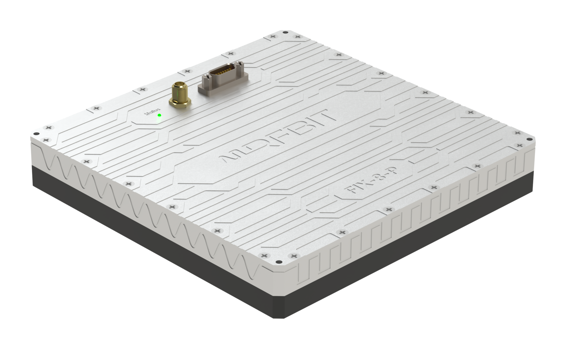
FIX GNSS anti-jam module
GNSS Anti-Jamming

FIX

Four to sixteen channels, single or dual band, from 80 mm and 105 g. Keeps the position when GNSS is jammed.

Explore FIX →
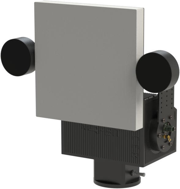
TRACER autotracking antenna pedestal
Autotracking Antenna

TRACER

RF monopulse pedestal. Reads the aircraft's bearing from the signal itself, so it keeps tracking where GNSS is jammed.

Explore TRACER →

ITAR-free

Designed and manufactured in Türkiye, free of ITAR-controlled content. Nobody in the supply chain can stop your programme for reasons that have nothing to do with it.

Ships in 8–12 Weeks

All three Bridge models ship 8–12 weeks from order. Output power is set in software after delivery, and all three run together on the same mesh.

Choose Your Configuration

Three models, one waveform, one mesh.

Bridge-2

2 × 2 W MIMO Mesh Data Link

Small UAS and SWaP-critical platforms, where every gram and every watt is contested.

Max RF Power2 × 2 W
Power Consumption—
Weight200 g
Dimensions130 × 90 mm
Bridge-2

Bridge-10

2 × 10 W MIMO Mesh Data Link

Tactical UAV and extended missions, where the link has to hold across the whole sortie.

Max RF Power2 × 10 W
Power Consumption—
Weight200 g
Dimensions130 × 90 mm
Bridge-10

Bridge-20

2 × 20 W MIMO Mesh Data Link

Ground station, relay and maximum-range nodes anchoring the mesh.

Max RF Power2 × 20 W
Power Consumption—
Weight200 g
Dimensions130 × 90 mm
Bridge-20

Specifications — Bridge-2

RF
Frequency Range400 MHz – 6 GHz
TX Channels2× TX (MIMO)
Output Power2 W per TX channel
Power ControlSoftware-adjustable
Spread SpectrumDSSS
Anti-Jam
Frequency HoppingAutomatic, full 400 MHz – 6 GHz
Hop Time1 ms
Hop CountUnlimited
Interference AvoidanceContinuous algorithm
Receive ChainPre-demodulator filter bank
Modulations
SchemesBPSK, QPSK, FSK, CPFSK, SOQPSK
High Order16QAM, 64QAM, 256QAM, 1024QAM
MulticarrierTD-COFDM
Network
TopologiesStar, line, network, hybrid mesh
Link TypesP2P, P2MP, MP2MP
RoutingLayer 2/3 dynamic, multi-hop relay
ArchitectureCenterless — no master node
EncryptionAES-256
Video & Telemetry
Camera InputFLIR raw over GigE Vision or USB
Raw Ingest500 Mbit – 1 Gbit
CompressionH.265 onboard, 1 – 3 Mbps out
RecordingSD card, in and out
TelemetryNative MAVLink passthrough
Interfaces
Data1× USB 3.2, 2× Gigabit Ethernet
Video In1× Micro HDMI
Serial2× RS232, 2× RS422/485
Bus2× CANbus
Discrete10× GPIO, 5 VDC-tolerant TTL
Connector51-pin micro-D
Power & Protection
Input Voltage12 – 36 VDC
ProtectionOVP, UVP, OCP, OSCP, OOLP
LineInrush current limiter
Pin ProtectionESD & lightning, every pin
Power Consumption—
Mechanical & Environment
Dimensions130 × 90 mm
Mass200 g
QualificationMIL-STD-810 tested
Altitude40,000 ft operational, passed
Onboard SensorsPressure, humidity, temperature, 9-DOF IMU
IndicationBuzzer, RGB status LEDs
Mechanical Drawing

Coming soon

3D Model

Coming soon

Connector Pinout

51-pin micro-D — pin assignment coming soon

Accessories

Part NumberDescription
——

Ordering Information

Part NumberRF PowerModel
—2 × 2 WBridge-2
—2 × 10 WBridge-10
—2 × 20 WBridge-20

Starting from $3,499. ITAR‑free, ships in 8–12 weeks.

Request a Quote

Compare Versions

Three models, side by side.

ParameterBridge-2Bridge-2Bridge-10Bridge-10Bridge-20Bridge-20
Max RF Output Power2 × 2 W2 × 10 W2 × 20 W
TX Channels2 (MIMO)2 (MIMO)2 (MIMO)
Frequency Range400 MHz – 6 GHz400 MHz – 6 GHz400 MHz – 6 GHz
Spread SpectrumDSSSDSSSDSSS
Frequency HoppingAutomatic, 1 ms hopAutomatic, 1 ms hopAutomatic, 1 ms hop
ModulationsBPSK, QPSK, FSK,
CPFSK, SOQPSK
BPSK, QPSK, FSK,
CPFSK, SOQPSK
BPSK, QPSK, FSK,
CPFSK, SOQPSK
High Order16QAM, 64QAM,
256QAM, 1024QAM
16QAM, 64QAM,
256QAM, 1024QAM
16QAM, 64QAM,
256QAM, 1024QAM
MulticarrierTD‑COFDMTD‑COFDMTD‑COFDM
EncryptionAES-256AES-256AES-256
TopologiesStar, line, network,
hybrid mesh
Star, line, network,
hybrid mesh
Star, line, network,
hybrid mesh
VideoH.265, 1–3 MbpsH.265, 1–3 MbpsH.265, 1–3 Mbps
Digital Interfaces1× USB 3.2, 2× GbE,
2× RS232, 2× RS422/485,
2× CAN, 10× GPIO
1× USB 3.2, 2× GbE,
2× RS232, 2× RS422/485,
2× CAN, 10× GPIO
1× USB 3.2, 2× GbE,
2× RS232, 2× RS422/485,
2× CAN, 10× GPIO
Connector51-pin micro-D51-pin micro-D51-pin micro-D
Input Voltage12 – 36 VDC12 – 36 VDC12 – 36 VDC
Power Consumption———
Dimensions130 × 90 mm130 × 90 mm130 × 90 mm
Weight200 g200 g200 g
Part Number———