HomeAboutProducts RF Antenna Tracker GNSS Anti-Jamming Modules MIMO Mesh Data Links IRIG-106 Telemetry Receiver IRIG-106 Telemetry Transmitters Video Encoders NewsCareersContact
TRS-1S · Telemetry

TRS-1S
Telemetry Receiver

The transmitter only has to leave the aircraft. The receiver has to recover the data after the link has been through range, multipath, antenna pattern nulls and airframe blockage — which is why the ground segment decides how much of a test flight is actually usable.
TRS-1S Telemetry Receiver

Chassis

Precision-Machined.
Two Finishes.

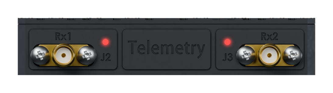
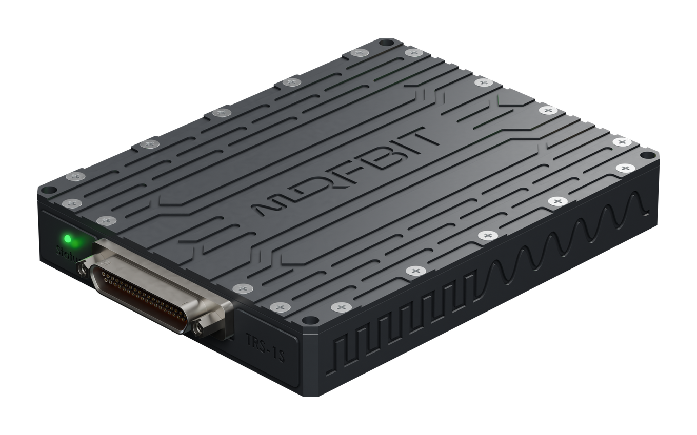
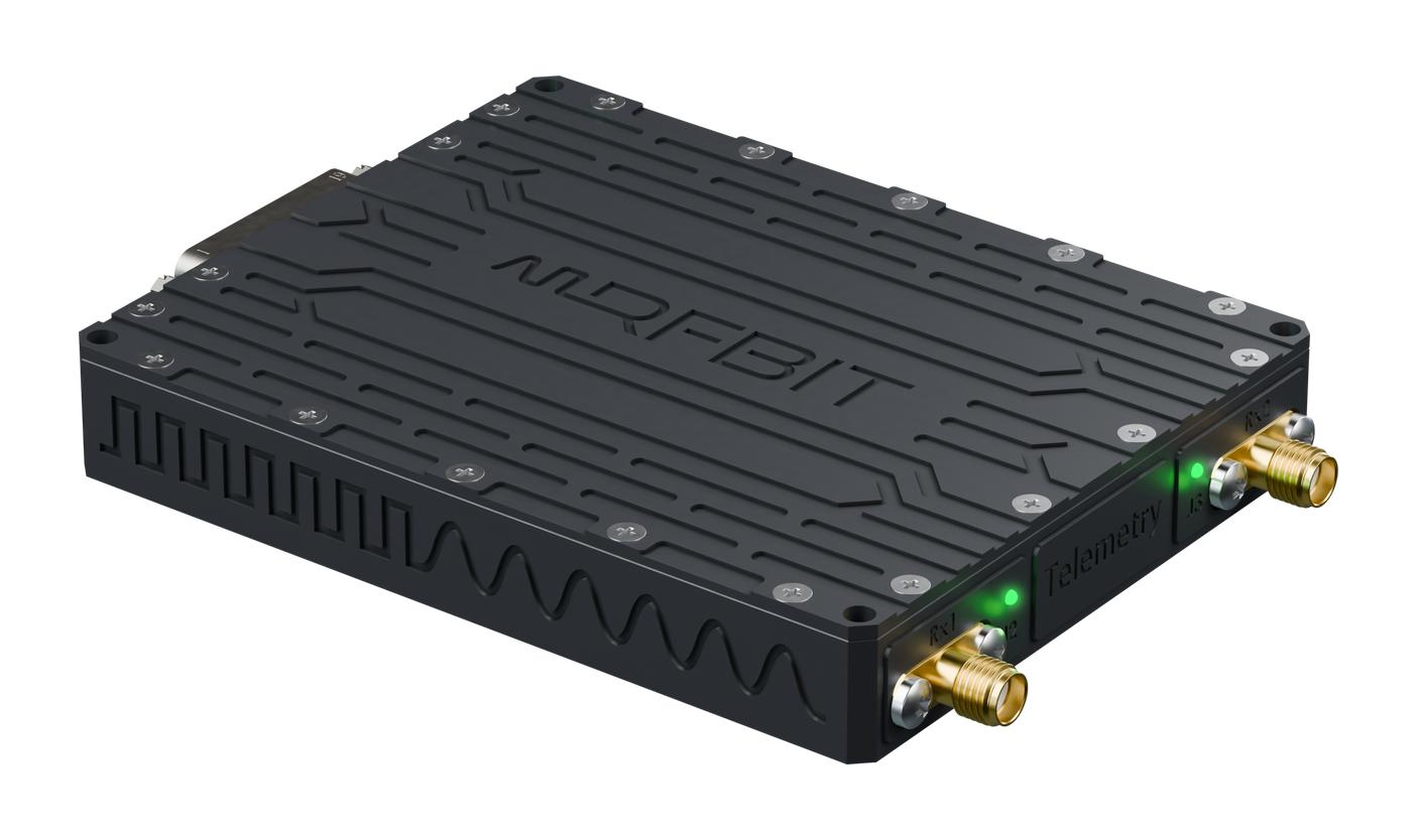
CNC-machined from solid aluminium in the same housing family as the TTS transmitters, so one bracket pattern and one harness style cover both ends of the link. The lid is cut as an integrated heatsink; the two RF inputs and the 25-pin Micro-D sit on opposite faces. Available in two anodised finishes.

Stealth Black

TRS-1S Telemetry Receiver
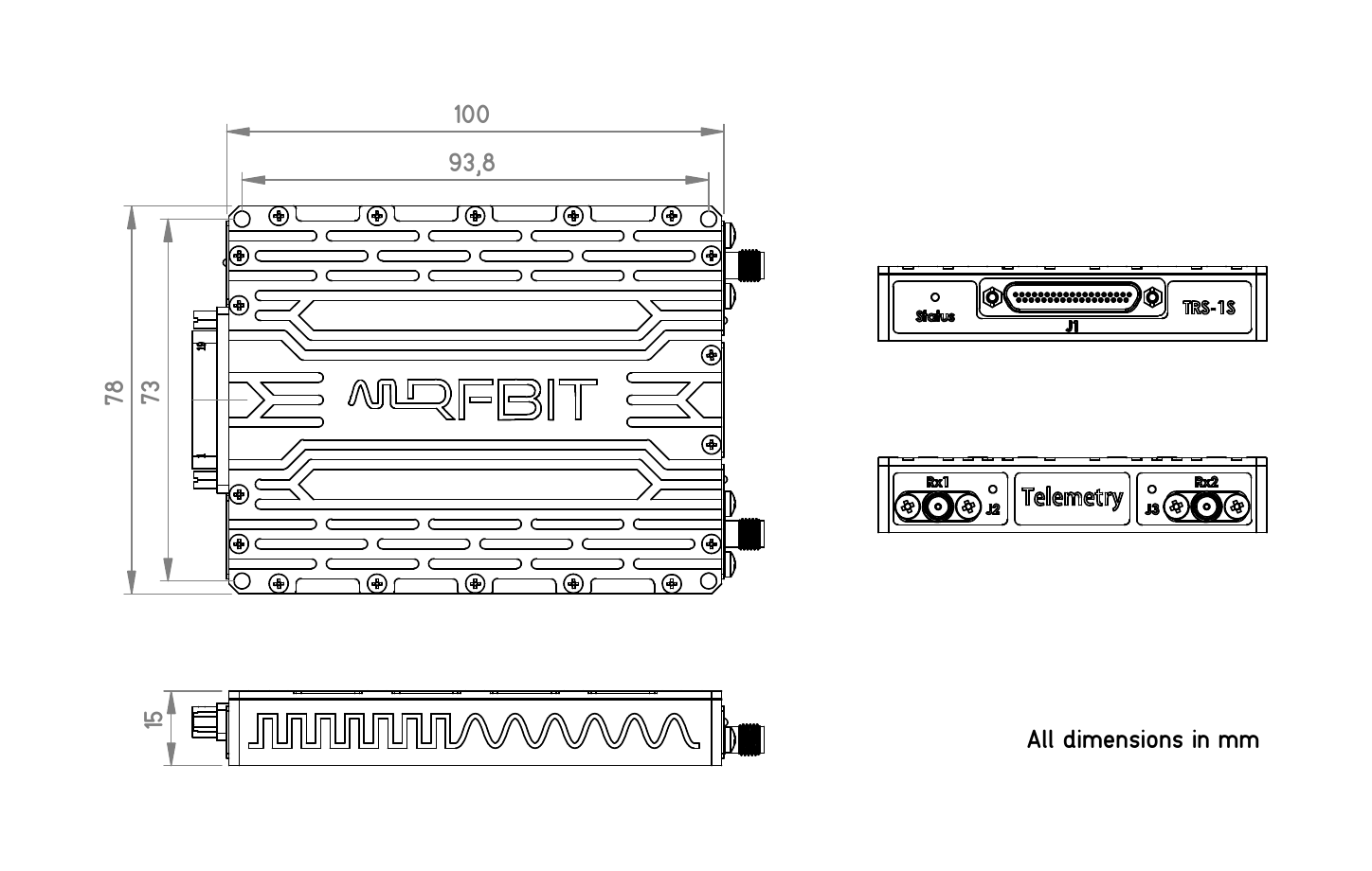
100 × 78 × 15mm
140 gWeight
2× SMARF Inputs (Rx 1, Rx 2)

Reception

Two chances
at every bit.

A single antenna on a moving airframe will find a null sooner or later. Diversity reception takes the signal from more than one antenna or receiver and combines them, so a fade on one path is covered by the other rather than becoming a dropout in the record.

Combining is done on signal quality, continuously. The output is a single recovered stream that is better than either input on its own — not a switch between them with a seam at every changeover.

DiversityMulti-Path Reception
CombinedContinuous Selection
Fade-TolerantNull Coverage

Signal Processing

Every waveform
the standard defines.

Reception covers the IRIG-106 waveform set, so the receiver matches whatever the airborne transmitter is configured to send rather than constraining the test to one modulation.

Bit synchronisation and clock recovery run on the demodulated stream, producing the clean, aligned data the downstream decommutation and recording chain expects.

IRIG-106Waveform Set
Bit SyncClock Recovery
AlignedDecom-Ready Output

Smart Diagnostics

System Health.
At a Glance.

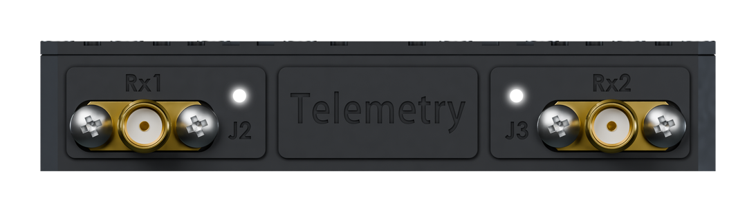
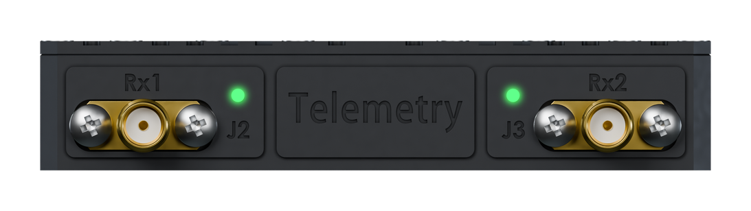
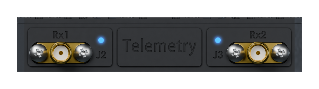
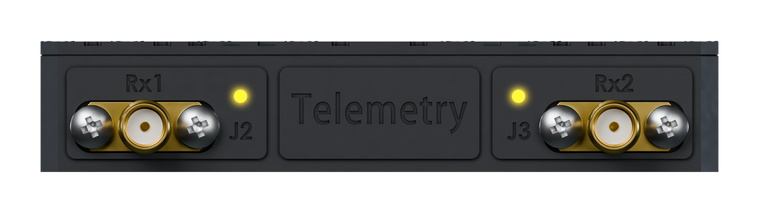
One status LED on the RF face reads out power, self-test, carrier lock and fault state — readable across the ground station without opening a terminal.

TRS-1S white LED TRS-1S green LED TRS-1S blue LED TRS-1S yellow LED TRS-1S red LED

Input power is present and the unit is booting. The LED holds white through power-up until the self-tests complete.

Deployment

Part of a chain,
not a box on its own.

A receiver is only as useful as its place in the ground station. Output feeds decommutation, recording and real-time display, while the antenna side works alongside the tracking pedestal that keeps the aperture on the aircraft.

Paired with a TRACER pedestal and a TTS transmitter, the TRS-1S completes a chain RFBIT builds end to end — one supplier for the airborne unit, the pedestal and the ground receiver.

End-to-EndTTS + TRACER + RX
DecomDownstream Feed
Real-TimeLive Display

Technical Data

Specifications

Figures for this product are issued with the datasheet. Contact RFBIT engineering for the current configuration.

Reception
Frequency Range—
WaveformsIRIG-106 set
DiversitySupported
Processing
Bit SynchronisationIntegrated
Data Rate—
Output Interfaces—
Mechanical & Environment
Dimensions100 × 78 × 15 mm
Weight140 g
Connectors1× 25-Pin Micro-D · 2× SMA (Rx 1, Rx 2)
Power—
Qualification—
Mechanical Drawing
TRS-1S Mechanical Drawing
3D Model
Loading 3D Model...
Drag to rotate • Scroll to zoom
Mechanical Drawing